Solid-State Architectural Lighting: Photometric Density, Thermal Dissipation, and Driver Topology in LED Cabinet Lights
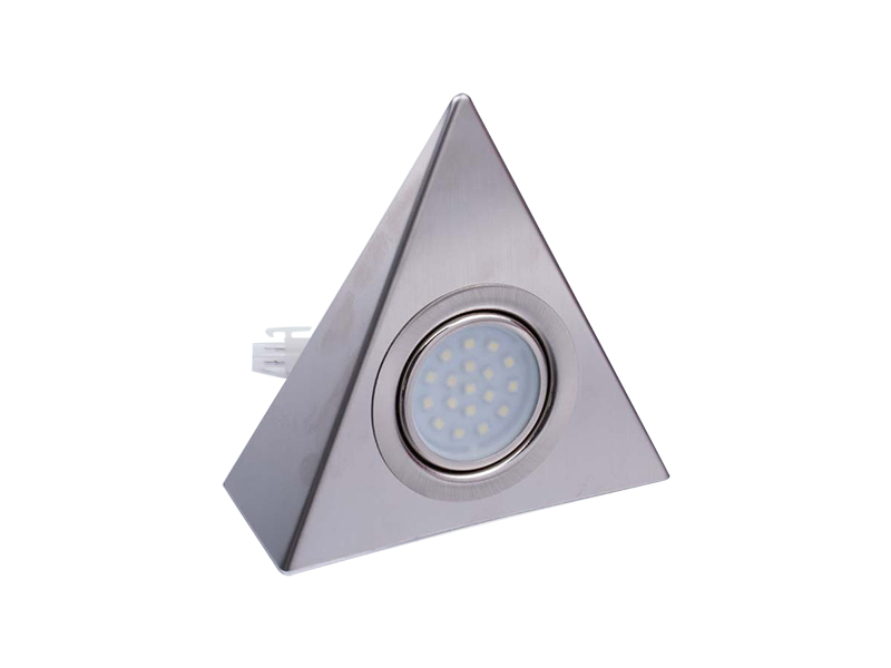
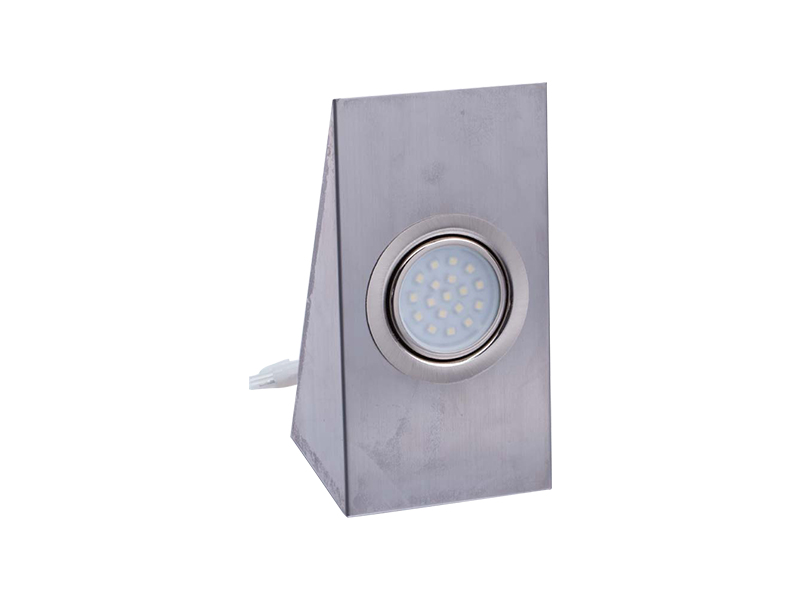
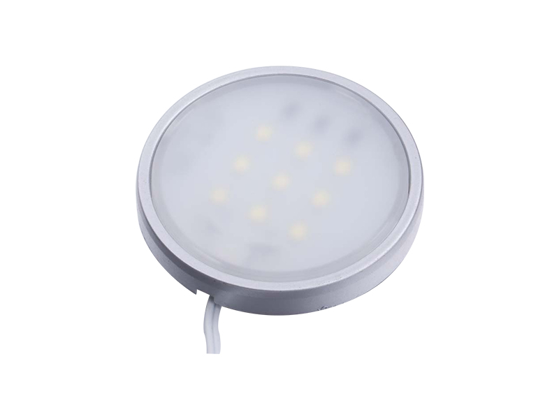
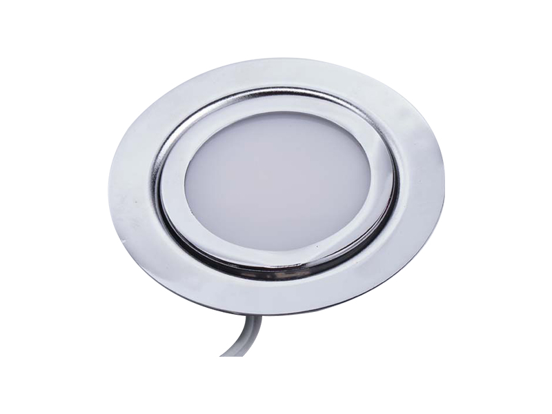
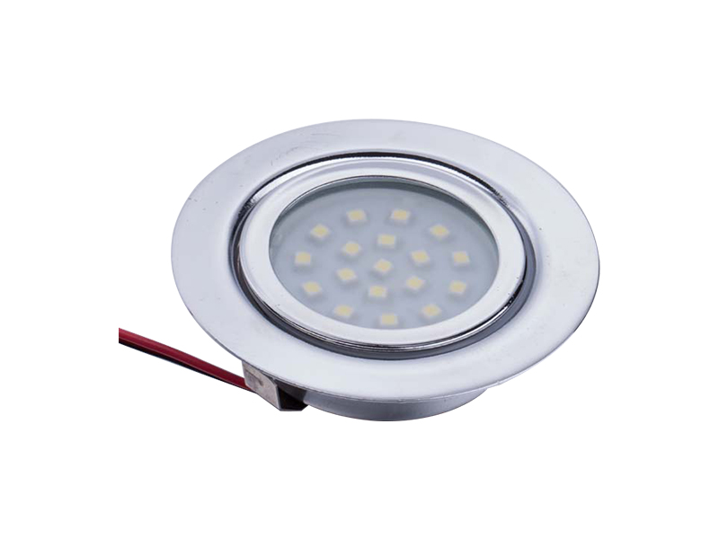
Optimizing workspace utility, interior visibility, and accent balance within modern millwork installations requires high-performance, low-profile illumination arrays. High-efficiency LED cabinet lights serve as the primary technical mechanism for removing shadows and dark zones created by deep overhead shelving units. By utilizing low-profile aluminum extrusion tracks or flush-mount puck designs combined with high-density surface-mounted diode (SMD) matrices, these micro-luminaire networks convert dark storage spaces into brightly lit, functional work surfaces while consuming minimal power and generating very little ambient heat.
Photometric Profiles and Spectral Waveform Accuracy
The practical success of an under-cabinet or inside-shelf light setup depends heavily on the color quality of its light source, especially when illuminating kitchen countertops or retail displays. Color fidelity is assessed using the international Color Rendering Index (CRI) $R_a$ value, paired with the specialized $R_9$ metric for deep red tones.
Standard, low-cost LED components often emit a sharp blue peak covered by a basic yellow phosphor layer. This simple design yields a low CRI score of 70 to 80, which distorts primary colors and makes objects look dull or unnaturally gray. To deliver professional-grade results, premium architectural cabinet installations specify high-performance diodes that achieve a minimum CRI rating of 90, with an $R_9$ red level above 50. This well-rounded spectral distribution ensures true-to-life color rendering, helping users prepare food safely, match materials accurately, and view merchandise with high clarity.
Correlated Color Temperature Interfacing Guidelines
Selecting the right Correlated Color Temperature (CCT) depends directly on the surface materials used in the cabinetry. For instance, dark wooden storage units or warm granite countertops pair best with a warm 2700K to 3000K light spectrum, which highlights organic grain patterns. Conversely, modern laboratories, hospitals, or minimalist white kitchens require a crisp, high-contrast 4000K to 5000K daylight profile to maximize visibility and support detailed task work.
Thermal Management and Substrate Heat-Sink Mechanics
A common misconception about solid-state lighting is that LEDs do not generate heat. While it is true that they emit a cool beam of light without infrared radiation, the internal p-n junction of the diode chip generates substantial localized heat that must be continuously dissipated.
If this internal junction temperature rises above 85°C, the semiconductor material begins to degrade rapidly. This thermal stress causes a drop in light output, shifts the color temperature, and can cut the system's operational life in half. To combat this issue, high-quality linear cabinet fixtures mount their flexible circuit boards inside rigid, anodized aluminum channels. The metal frame acts as a highly efficient heat sink, drawing thermal energy away from the delicate chips and radiating it safely into the surrounding air. This active thermal management keeps the diodes running cool, ensuring the system reaches its full 50,000-hour operational lifespan.
Low-Voltage Power Topologies and Dimming Circuits
Cabinet lighting networks are designed to operate using safe, low-voltage electricity, keeping high-voltage alternating current (AC) lines away from close-contact work surfaces and wood storage bays.
The system relies on an external power supply or driver to step down high-voltage building current into regulated 12-Volt or 24-Volt Direct Current (DC) lines. Choosing a 24V DC layout offers a clear technical advantage for larger installations because it halves the electrical current moving through the circuit compared to a 12V system. This reduction in current prevents voltage drop along extended wiring paths, ensuring the LEDs at the far end of a long counter run remain just as bright as the ones closest to the power source.
Pulse Width Modulation vs. Constant Current Reduction
To dim cabinet lights smoothly without shifting their color temperature, advanced driver circuits use Pulse Width Modulation (PWM) running at high frequencies exceeding 20 kHz. This rapid, microscopic switching cycle adjusts brightness without creating visible strobe effects, preventing eye fatigue and avoiding interference with digital screens or video recording equipment in the room.
Performance Specifications and Mechanical Layout Matrix
Specifying lighting equipment for residential home projects or large-scale commercial developments requires a precise review of core engineering metrics. The chosen components must deliver adequate surface illumination without overloading power supplies or violating local building energy codes.
The table below outlines the primary electrical, optical, and physical dimensions for professional-grade LED cabinet lighting systems used in modern architecture:
| Fixture Structural Type |
Linear Packing Density |
Luminous Output Rating |
Operating Input Voltage |
Max Continuous Run Limit |
| High-Density Linear Tape |
120 to 240 diodes / meter |
350 to 600 lumens / foot |
24V DC Constant Voltage |
10.0 Meters (32.8 Feet) |
| Standard Accent Linear Strip |
60 to 90 diodes / meter |
150 to 300 lumens / foot |
12V DC Constant Voltage |
5.0 Meters (16.4 Feet) |
| Recessed Circular Puck Light |
Cluster Arrays (Multi-Die COB) |
200 to 350 lumens / unit |
12V or 24V DC Low Voltage |
Limited by driver current capacity |
Table 1: Photometric density values, electrical voltage boundaries, and single-feed maximum length limits calculated under international architectural lighting standards.
Optical Diffusion Technology and Hot-Spot Mitigation
Mounting a raw, uncovered LED strip inside a cabinet often causes glare issues. The bright, exposed diode points reflect harshly off shiny surfaces like polished quartz, marble, or glass countertops, creating distracting hot spots that disrupt the look of the room.
To solve this problem, modern lighting systems hide the LED strip behind a curved, milk-white diffuser cover made from high-grade Polymethyl Methacrylate (PMMA). This diffuser lens is filled with microscopic light-scattering particles that bend and blend the sharp, individual light beams. This process shifts the light output from harsh, separate points into a smooth, continuous line of light. To completely eliminate hot spots, installers combine these frosted lenses with high-density tape lights that place the diodes close together, creating a seamless, high-quality glow across the entire work surface.
Structural Installation Protocol and Low-Voltage Wiring Integration
Installing an integrated low-voltage cabinet lighting layout requires following clear structural and electrical steps. Proper planning and precise wire routing prevent early component failures and keep the installation looking clean and professional.
- Map Output Zones and Locate Power Feeds: Inspect the cabinet layout to choose the best mounting locations. Place the lights near the front edge of the upper cabinet undersides to cast light evenly across the counter workspace, and select an accessible, well-ventilated storage bay or pantry closet to house the central power driver box.
- Route Conduits and Drill Access Holes: Use a wood spade bit to drill 10mm to 12mm holes through the hidden bottom corners of the cabinet frames. Route low-voltage wires through these entry points, keeping the wires hidden out of sight behind the lower cabinet valance or face molding.
- Secure and Align Aluminum Mounting Tracks: Cut the aluminum profile channels to the exact length of each cabinet section using a fine-toothed hacksaw. Secure the metal channels flush against the wood surfaces using flathead countersunk screws, ensuring the tracks are straight and securely mounted.
- Adhere LED Strips and Snap Diffusion Covers in Place: Clean the inside of the aluminum tracks with isopropyl alcohol to remove all wood dust and grease. Peel off the adhesive backing from the LED tape, press it firmly down along the center of the metal channel, splice the wire leads, and snap the frosted PMMA diffuser cover into the track over the diodes.
- Wire Connections and Calculate Total Power Load: Connect the individual wire runs back to the main DC power supply, wiring the sections in a parallel layout. Double-check that the combined power load of all attached lights stays at least 20% below the maximum watt rating of the driver, preventing overloads and ensuring stable system operation.
Root Cause Failure Analysis and Troubleshooting Routines
When an integrated low-voltage cabinet lighting layout begins to malfunction, maintenance technicians can quickly diagnose and resolve the problem by identifying specific electrical failure symptoms.
A common issue is a noticeable drop in brightness toward the end of a long, single-feed line. This symptom is a classic sign of structural voltage drop, which happens when installers push too many linear feet of tape light through a single power feed. As electricity travels through the thin copper traces of the circuit board, the metal's natural resistance reduces the voltage along the run, leaving the far diodes dim. To fix this, technicians must reconfigure the wiring layout, splitting long runs into shorter sections and routing a dedicated home-run wire from the main power supply to both ends of the light chain to equalize voltage.
Another common failure mode occurs when an entire section of lights shuts down completely while other parallel groups stay fully lit. This sharp failure typically points to a broken solder joint or a failed mechanical snap connector at the start of that dark section. If a cabinet door slams hard or a wire is pulled during cleaning, the physical strain can snap the thin copper connections on the flexible circuit board. Technicians can find the point of failure by testing the line with a digital multimeter, cutting away the damaged segment, and soldering fresh wire leads onto the next set of copper pads to restore full operation.


 English
 Español
 中文简体
中文简体